


- Applications
1. Overview
Fast Recovery Diodes (FRD) are semiconductor devices with fast reverse recovery characteristics, widely used in high-frequency switch-mode power supplies, inverters, motor drives, and other circuits that require rapid switching. This guide aims to help engineers understand the characteristics of FRDs, selection methods, and precautions for practical applications.
2. Basic characteristics of FRD
2.1 Reverse recovery time (trr)
· Definition: The time required to clear a few electrons stored when switching from forward conduction to reverse blocking.
· Importance: The shorter the trr, the faster the FRD switching speed, suitable for high frequency applications.
2.2 Reverse recovery peak current (Irr)
· Definition: The maximum value of reverse current during reverse recovery.
· Importance: The larger the Irr, the higher the reverse recovery loss, and the appropriate FRD should be selected according to the circuit requirements.
2.3 Reverse recovery charge (Qrr)
· Definition: the total charge flowing during reverse recovery.
· Importance: Qrr is a key parameter for calculating reverse recovery loss, which affects the efficiency and the thermal design of the circuit.
2.4 Forward voltage drop (VF)
· Definition: The voltage drop of FRD when it is forward conducting.
· Importance: The smaller the VF, the lower the conduction loss, suitable for high efficiency circuits.
3. Selection method of FRD
3.1 Determine the working voltage
· When selecting FRD, its maximum reverse voltage (VR) should be higher than the maximum reverse voltage in the circuit, usually leaving a margin of 20%-30%.
3.2 Determine the working current
· The rated forward current (IF) of FRD should be higher than the maximum forward current in the circuit, usually with a margin of 20%-30%.
3.3 Select reverse recovery time
· Select an appropriate Trr according to the switching frequency of the circuit, and select a FRD with a shorter trr for high frequency applications.
3.4 Consider thermal design
· According to the power consumption, thermal resistance and working calculated junction temperature of FRD, ensure that it is within the safe operating temperature range.
In FRD application, in addition to forward conduction loss, reverse recovery loss is also very important. The overall loss of diode is mainly determined by these two factors. In the application, it is necessary to evaluate whether the Trr selection of FRD is appropriate according to the actual situation.
In the ideal reverse recovery waveform, the loss generated by reverse recovery:
Psw-off≈Vrp*Irrm*Trr*fsw/2
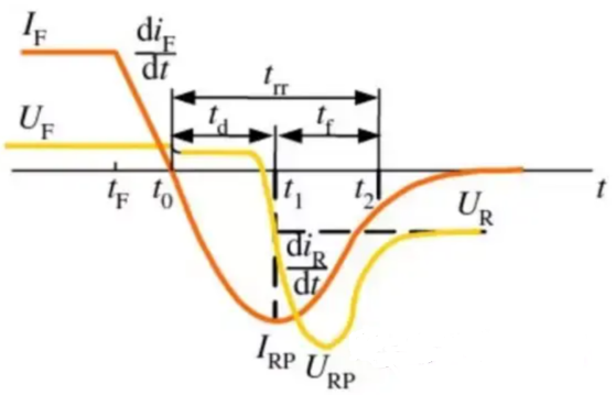
In the actual reverse recovery, Vrp is close to Vr, and the loss generated by reverse recovery is:
Psw-off≈Vr*Irrm*Trr*fsw/2.
Regardless of any waveform, for high frequency applications, it is necessary to evaluate whether the overall power consumption of the device exceeds the limit and whether there is a risk of thermal runaway.
Overall power consumption of the device: PD= Pon + Poff + Psw-on + Psw-off (where Poff is small because of the low leakage current, and Psw-on is also small because of the short time, the forward voltage drop is low, so the power consumption generated by both can be almost ignored, but Psw-off needs to be calculatedd the value at high temperature, the higher the temperature, the larger Trr, and the larger the Psw-off will be)
According to the thermal resistance, calculate the corresponding temperature rise: DT=PD * Rth jc
According to the actual working temperature of the device, calculate the junction temperature of the device: Tj= T c + DT
Ensure that the junction temperature (Tj ) of device does not exceed Tj max, and has a certain margin.
The following two FRD devices have the same current and voltage, and the difference of Trr is small, but the reverse recovery loss is quite different. Furthermore, under high temperature, the difference will be further bigger, resulting in the power consumption difference brought by this cannot be ignored.
|
Specification parameters |
Rg1-Trr(ns) |
VF(V) |
VRRM(V) |
IF(A) |
|
A |
34 |
1.7 |
600 |
8 |
|
B |
25 |
1.9 |
600 |
8 |
|
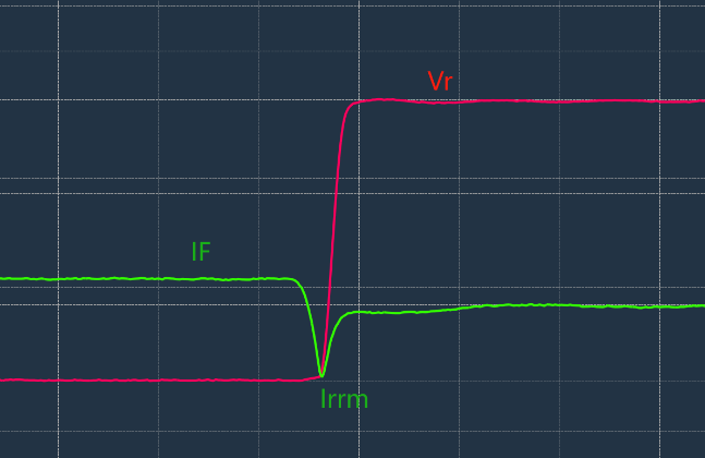
Test Trr in practice |
|
Irrm |
Trr |
Qrr |
|
IF=5A,VR=200V,di/dt=100A/us |
A |
1.9 |
62 |
61 |
|
B |
0.5 |
36 |
10 |
At 5A/200V, frequency 65KHz application, to calculate the reverse recovery loss:
To sample A, the reverse recovery loss Psw-off is 0.77W, while to sample B, the reverse recovery loss Psw-off is 0.12W
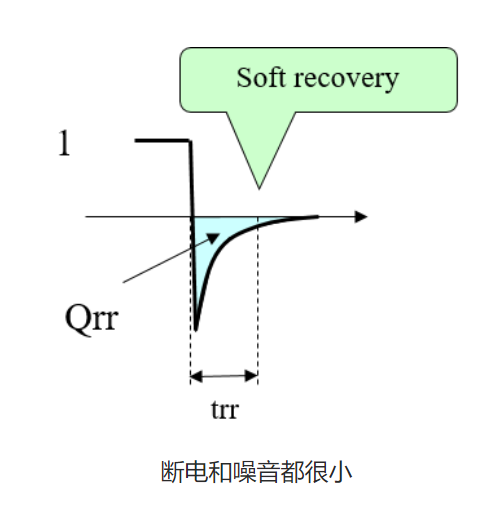
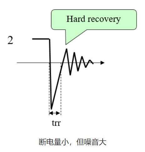
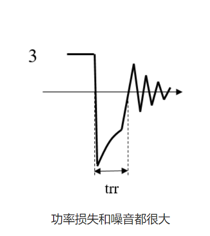
Soft recovery and hard recovery
When the current recovery is too abrupt, it generates more noise. Therefore, Trr should not only be small but also require a slower recovery. The pic 1 and 3 may appear to have the same Trr in specifications, but their losses and noises are quite different. Moreover, the pic 2 looks very good when reviewing specifications, but it produces significant noise.
|
|
|

